Measurement of micro-g acceleration
Project summary
The sensitivity of atom interferometers is usually limited by the observation time of a free-falling cloud of atoms in Earth`s gravitational field. Considerable efforts are currently made to increase this observation time, e.g. in fountain experiments, drop towers and in space. In this article, we experimentally studied and discussed the use of magnetic levitation for interferometric precision measurements.
We used a Bose-Einstein condensate of cesium atoms with tuneable interaction strength and a Michelson interferometer scheme for the detection of micro-g acceleration. In addition, we demonstrated observation times of 1s, which are comparable to current drop-tower experiments. We also studied the curvature of our force field and observed the effects of a phase-shifting element in the interferometer paths [New J. Phys. 21, 053028 (2019)].
Motivation
Atomic fountain interferometers have demonstrated an staggering measurement precision of order Δg/g~10−10. This project does not aim to compete with atomic fountains, but we were curious to test the limits of out magnetic field control in the lab. Most of the technical work is centered around measuring and controlling current in coils, and determining magnetic field gradients and curvatures. Our take-home message from the project was: magnetic field stabilization with 10-5 precision for levitation is moderately easy, a 10-6 precision is do-able, and less than 10−7 will get really hard and tedious.
Interferometer scheme
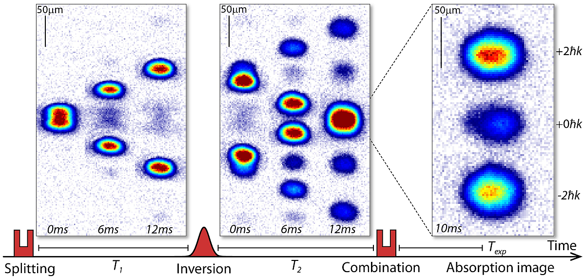
We employed a Michelson interferometer scheme that is based on three Kapitza-Dirac pulses with a standing light wave [PRL 56 827 (1986), PRL 75 2633 (1995)]. The pulses change the motional states of the matter waves but leave the internal states of the atoms unchanged. Our pulse sequence and the resulting motion of the matter wave packets are illustrated in the figure below. A first pulse splits the BEC into two wave packets with opposite momenta. The wave packets propagate freely for an evolution time T1 until we apply a second pulse that inverts the direction of the wave packets and changes their momentum again. A third pulse is used after an evolution time T2 to recombine the two wave packets. It is identical to the first pulse and generates three wave packets with momenta p0 = 0, ±p. The acquired phase difference ΔΦ between the wave packets can be determined from the relative population of the recombined wave packets on an absorption image.

Absorption images of 3-pulse Michelson interferometer scheme
Acceleration measurement
The acquired phase difference ΔΦ between the wave packets increases with hold time for external forces. Large forces make ΔΦ oscillate quickly between 0 an 2pi, while small forces result is slow oscillations. The figure below shows this oscillation of ΔΦ (measured by the relative population of the wave packets) for decreasing forces (a,b,c). We experimentally created the forces be changing our levitation current, and thereby changing the levitation gradient, to ΔI/I_lev of (a) 0.003, (b) 0.001, (c) 0.0003. Subplot (d) shows a comparison of the acceleration measurement with the interferometer scheme (red circles) and by a different measurement approach using the center-of-mass motion of a BEC (blue diamonds).
We determine an upper limit for the acceleration of the atoms of 70(10)x10−6g. To the best of our knowledge, this is the smallest absolute value for an acceleration that is measured directly with ultracold atom interferometry. However, the goal of the project is to evaluate the limits, and the article provides a long discussion of technical reasons that limit the measurement precision.
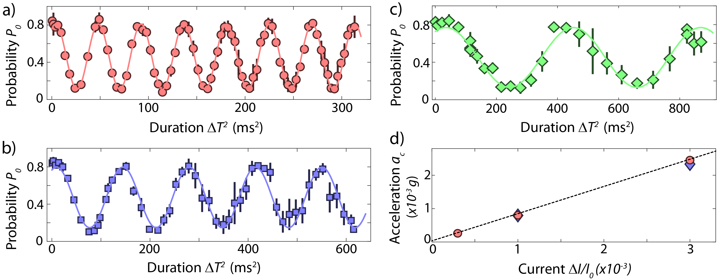
Oscillation of the phase and population difference for various accelerations
Measuring other potentials
After benchmarking the measurement scheme, we started to play with our setup. The figure below shows a measurement of the phase shift that is created when the BEC propagated through another laser beam. Subplot (a) shows the phase shift for minimized acceleration of the atoms (red circles) and for the addition laser beam in the path of the upper wave packet (blue squares). Subplot (b) illustrates of the path of the wave packets and the additional laser beam during the pulse sequence. Angles and axes are not to scale in the illustration.
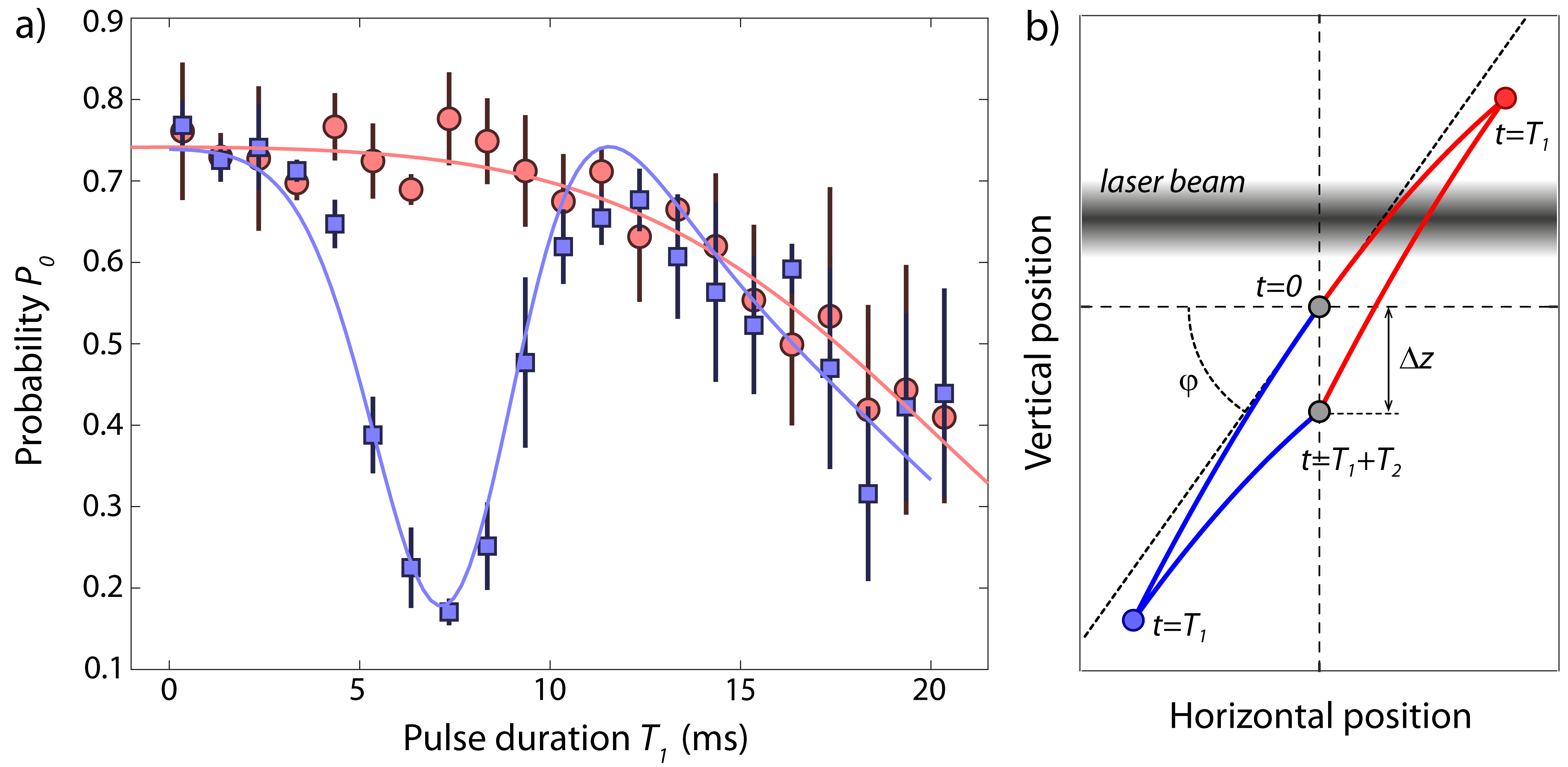
Phase shift due to an additional laser beam in the interferometer.
Free vertical expansion of a BEC
Finally, after having minimized residual acceleration with the interferometric measurement scheme, we tried to maximize the evolution time of the BEC with free vertical expansion. Long observation times of an expanding BEC facilitate a sensitive acceleration measurement approach, too. We demonstrate in the article that magnetic levitation allows us to extend the vertical expansion time of a BEC to 1s, and we evaluate advantages and limitations of this scheme for precision measurements.
Typical expansion times for falling BECs are on the order of tens of milliseconds, often limited by the detection area of the imaging system, by the gravitational acceleration and by the expansion velocity of the gas. Usually, the expansion velocity of a quantum gas is not caused by the temperature of the gas but by repulsive interaction during the initial spreading. The current record for long observation times under milli-g acceleration is 1s [Science 329 1540 (2010)]. The experiment was performed in a drop tower, and ballistic expansion was observed over approximately 500 ms, limited by stray magnetic fields. We demonstrate similar observation and expansion times (figure below) for levitated BECs. Sub-panel (a) shows averaged absorption images, (b) measures the broadening of the expanding BEC, and (c,d) show vertical density profiles for expansion times of 400ms and 600ms.
There is a clear kink in the density profile in sub-panel (d). We failed to explain this kink properly at the time of writing the article. It is caused by a position dependent interaction strength due to our levitation gradient. This observation lead to another project and to another article [Phys. Rev. Lett. 125, 183602 (2020)].
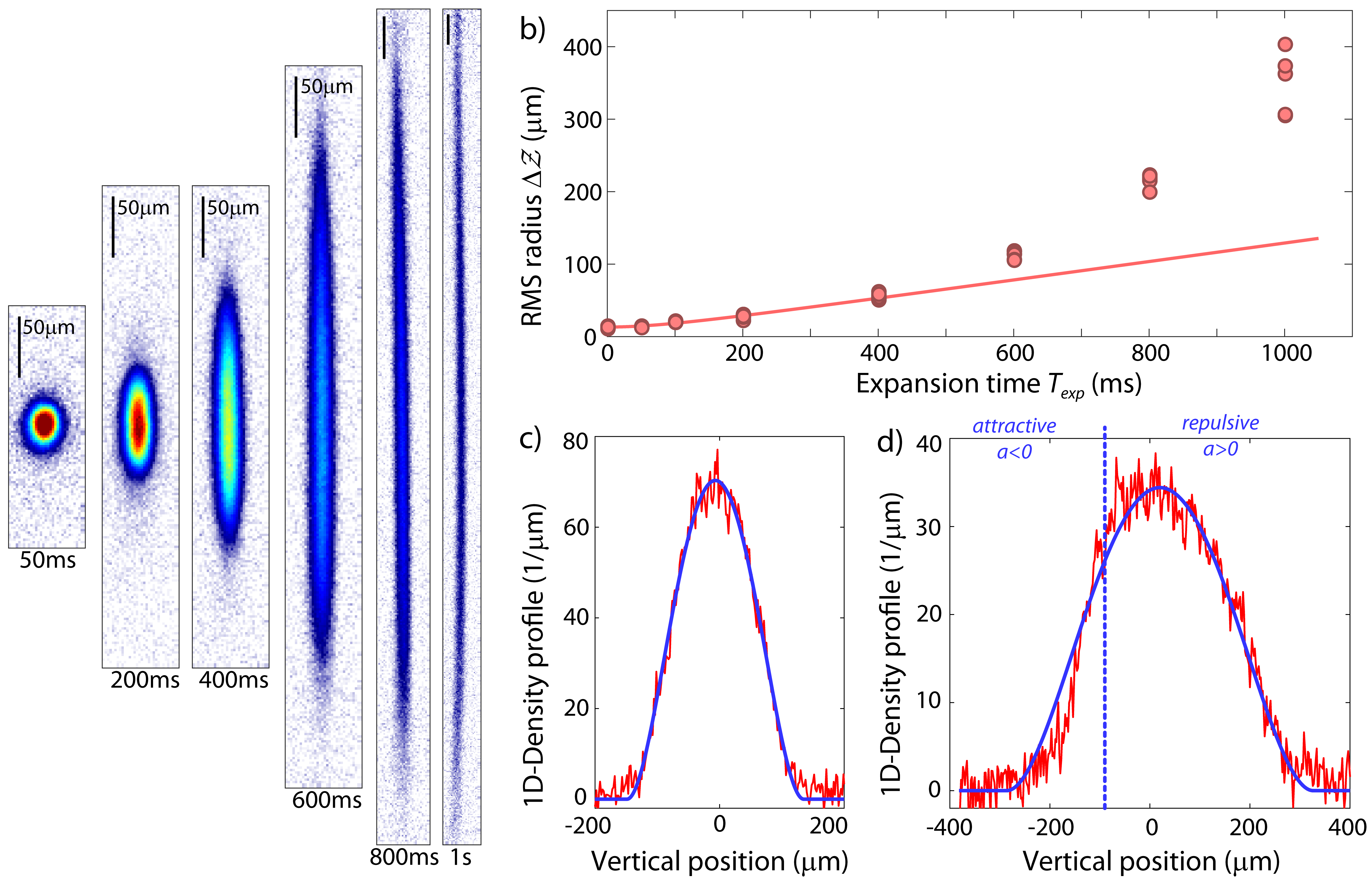
Long vertical expansion of a BEC